Working With PRUs @BeagleBoneBlack : Introduction To PRUs
This is the first in a series of posts to explain and provide with some basic examples to work on PRU cores in AM335x. The AM335x SoC can be found on famous embedded board BeagleBone Black. The post are:
Introduction to PRUs (this) To make you comfortable with the concept of realtime systems with PRUs, and basic introduction to various peripherals in the PRU-ICSS subsystem.
Remoteproc To explain the working of remoteproc Linux driver to manipulate remote processing unit ie PRU for AM335x SoC. This post will provide a logical framework first, and then will dive into the driver’s code.
RPMsg Framework Till this post, you will have understanding of how PRUs are booted up and start executing the firmware loaded onto them. This post will further explain the RPMsg way of communication between main processing unit and the PRUs.
In all these posts, I will be using softwares (kernel images, compilers etc ) that are recommended by BeagleBoard.org. This post is just an introduction to PRUs, so is anyway useful. Some of the reference that I have used throughout these posts are :
Prelude
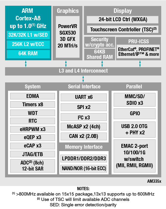
Texas Instruments has this series of processors based on ARM Cortex-A core they call TI’s Sitara Processors. One of these processors that is used in the microcomputer board BeagleBone Black is AM335x . These processors have a very interesting subsystem called PRU-ICSS as can be seen in top right in the figure below.

It can be thus said that AM335x has 3 processing cores. Two of them are enclosed in the PRU-ICSS subsystem and are called PRUs, operating at a clock speed of 200 MHz each. The other is the ARM Cortex A8 main processing unit or MPU for short, at 1GHz. This A8 MPU is a high end processor and can have an OS like ubuntu, debian or android running on it. The MPU with all high end processing stuff like caches and pipelines has a lot of limitations regarding to its realtime use. Comes to rescue, the PRU aka Programmable Realtime Units that are present on the same SoC.
At this point, I would like to explain what I mean by “realtime use”. Imagine two events ‘crashing of a car’ and ‘opening up of the air bags’. The time delay between two events should be very much deterministic as its the matter of someone’s life. This is the point where a computer system with deterministic delays, between the input and producing the desired output is needed. In simple terms, realtime systems are used in the arrangements where something critical, in terms of time delays, need to be done. For a realtime system, a developer can easily determine the maximum time delay between a stimulus and its response.
A general purpose OS’s kernel is a combination of some core management softwares along with the softwares to manage and control the hardware. The core part of the kernel has something called scheduler. It schedules various tasks that appear to run simultaneously on a computer system. Scheduler does this using various algorithms. This makes it almost impossible for a developer to determine the time delay between an input and its output. Even in case of interrupts in general OS, the ISR just notifies the system of interrupt and places the required task in scheduler’s queue. Further, availability of hardware features like caches and pipeline system adds to this difficulty in latency determination. There are realtime versions of operating systems too, that allow one to determine the max-latencies, but it has its own cons. The best is to use an independent realtime unit. If you need more justification on why to use a realtime system, see this video by Linux foundation .
PRUs
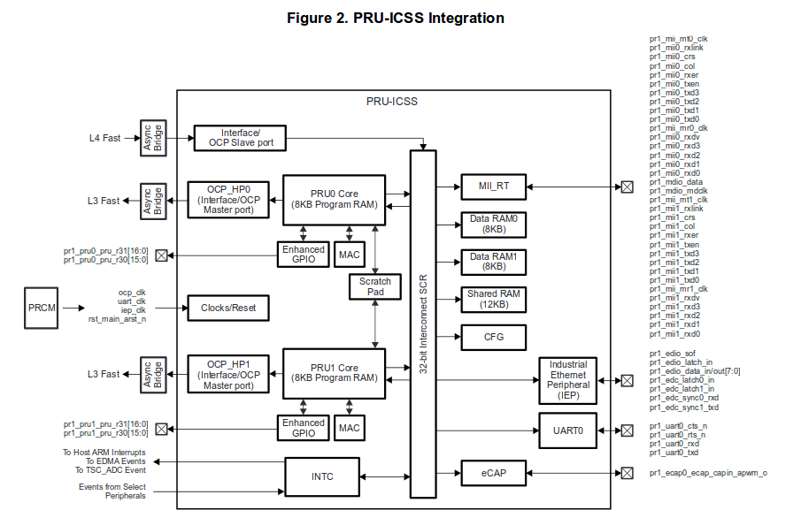
The two PRUs enclosed in the PRU-ICSS subsystem are specially designed for high speed, low latency, realtime processing. PRUs are basically 32 bit RISC processors that can work independent of the MPU. As is shown in the figure below, there are many more peripherals that are enclosed in the PRU-ICSS unit. Integration of all these peripherals in the PRU-ICSS aims to make realtime processing easy, reliable and fast. After all that “realtime” stuff above, you may ask, “How does the PRUs make realtime thing possible ? after all they are yet another processing core.” Well, No, they are not “yet another” processing unit, but are special kind of processing unit. They have very limited yet enough number of instructions to program with and almost all of them get executed in single cycle (ie 5 nSec). Each instruction has a perfectly deterministic latency (provided its accessing PRU-ICSS resources, more on this later), has no caches or pipelines and is equipped with enhanced GPIO unit. Using PRUs, you can toggle a GPO at about 50MHz, and believe me, thats a great thing for a SoC having a general purpose OS on it.
This figure down here may look a bit complex, its rather simple and will be very useful once you understand it.

[Note: This post is just to make you comfortable with PRUs for further experimenting and learning, so we are not going to go into deep details of various peripherals in PRU-ICSS. I am just going to give an overview of some of them. We will learn how to use various peripherals in later posts.]
So lets go ahead and understand some of the most used peripherals inside PRU-ICSS with reference to the above figure:
PRU0 and PRU1 cores : These are the 2 PRU ( Programmable Realtime Unit ) cores we have been talking about. They are 32-bit processors based on RISC design strategy. As a result, they need just a handful of assembly instructions to program them, and most of them, as already stated earlier, execute in one single cycle. The two PRUs are identical in every aspect. Each one them has 8K bytes of program RAM aka instruction RAM or iRAM for short. Apart from the iRam, they have 30, 32-bit general purpose registers in each of them.
Enhanced GPIO : You can see a block named Enhanced GPIO directly connected to each of those PRU cores in the figure. The word “Enhanced” is used because of some nifty modes that they have. They are:
Direct Mode : In this mode, all the GPIOs are directly connected to the PRUs internal register. That basically means that whenever the PRU reads the register associated with the GPI, it gets the instantaneous value of the GPI. Same is the case with output, whatever is written to output associated register, appears directly on the GPOs.
Parallel Capture mode (input only): In this mode, one of the GPI is used as an external strobe and other GPIs to capture data. That basically means, the data will be automatically captured by the GPI module when, for example, there is a positive rising edge on its external strobe pin.
28-bit Shift (input only) : Each PRU has got a shift register that can be used in this mode of operation, to get serial data as input from one of its input pins. The sampling rate can be varied using clock divisors inside the PRUs.
Shift out (output only): This mode is kind of opposite to the 28-bit shift mode, such that, in this mode, the shift register is used to output serial data through one of its GPO.
OCP ports : The OCP ports (Open Core Protocol ports) are generally used for communication between various subsystem on the same chip. So as you might have already guessed, these ports are used to communicate with other subsystems, external to the PRU-ICSS, that are present on the SoC. These ports allow PRU to SoC peripheral (RAM, SPI unit, ADC etc) communication, or A8 MPU to PRU-ICSS peripheral (shared RAM, INTC, instruction RAM etc) communication. The OCP master port is for PRU to external peripheral (via L3 connect bus) communication and OCP slave port is for External peripheral to PRU-ICSS peripheral communication (via L4 connect bus).
INTC : This is an Interrupt controller to manage interrupts from one PRU to other, from PRU to external peripherals or from external peripherals to PRU. At this point you may ask that, for example PRUs are doing some critical job and get interrupted, how does that make it deterministic and reliable for realtime systems ? Well, interrupts on PRU are not interrupts in classical sense. Occurrence of an interrupt does not actually interrupts the current execution, but it sets an known bit, which needs to be checked by the software on the PRU to perform related task. So for example, if the PRU is doing a critical job, it might detect the interrupt by checking that interrupt-related-bit and choose not to do anything for now, or it might not even check that bit while its doing those critical jobs. There is more to INTC, but thats for later.
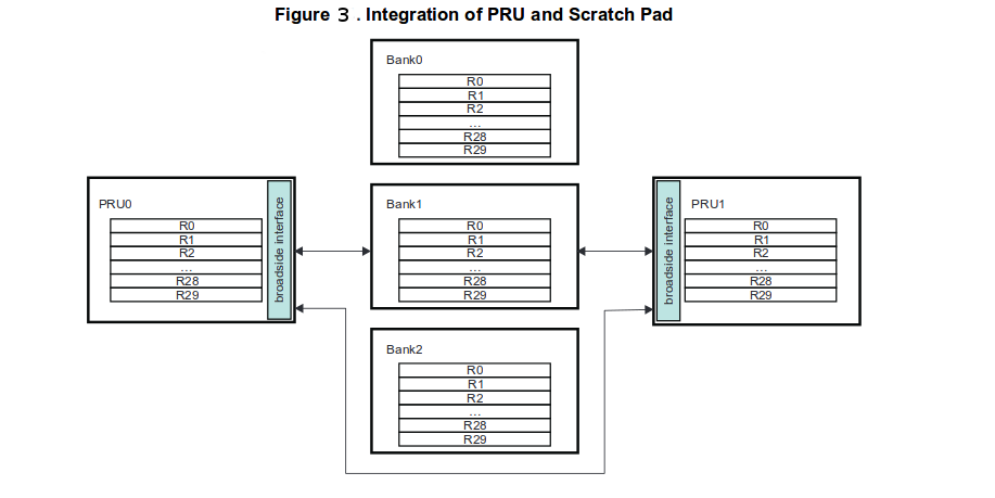
Scratch Pad : One of the nifty features that PRUs have is the presence of scratch pad. Its a set of 3 banks, with 30, 32 bit registers in each. The most interesting thing about these scratch pads is their broadside interface, which allows swapping of all these 30 registers, between PRU0 and PRU1 or between PRU-n and Bank-m, in just one single cycle. Isn’t that cool ! The figure shows this arrangement of registers and scratch pad.

In addition to all this, PRU-ICSS unit also has MAC (Multiplier - Accumulator unit) for each of the PRUs, a CFG unit that contains various configuration registers and a few more peripherals. We will further see how to use PRUs and various in-PRU-ICSS peripherals to make a realtime system in posts ahead.
So thats all for this post. Next to it is this post explaining remoteproc, Linux way of working with PRU.